
Sawtooth velvet stripping machine The structure and function of MR-D sawtooth velvet stripping machine
There are many types of mechanical velvet stripping machines. According to the different stiffness of the main working parts of the machine, they can be divided into rigid working parts (such as sawtooth stripping machines and abrasive stripping machines) and elastic working parts (such as wire brush roller stripping machines). Velvet machine) two categories. Among them, the sawtooth velvet stripping machine with rigid workpiece parts has higher production efficiency and better adaptability. It is the main velvet stripping machine used in my country.
There are many types of sawtooth velvet stripping machines. According to the brush type, there are brush type and airflow type; according to the number of saw blades, there are 200 type, 176 type, 160 type, 144 type, 141 type and other types; The number of layers is divided into single layer type, double layer type and three layer type. Currently, the MR-141 and MR-144D sawtooth stripping machines are most commonly used. In addition, the 6MRQ-141A, 6MR160D-10 and MR200-10 are also commonly used.
1. The structure and function of the MR-144D sawtooth velvet stripping machine
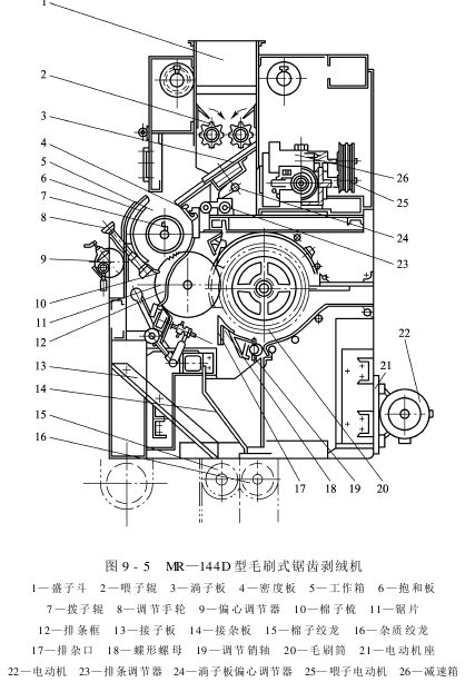
The MR-144D brush sawtooth velvet stripping machine is shown in Figure 9-5. The cotton seeds transported by the auger enter the hopper to prepare the material source for stripping down. Driven by the automatic control motor, the feeding roller passes through the reduction box and is transmitted to the feeding roller at a low speed. The feeding rollers rotate in opposite directions in the feeding bucket, leaking the cotton seeds and falling on the drain plate, passing through the drain plate. Entering the working box, the clean cotton enters the working box and forms a cotton roll through the stirring of the pick roller and the hooking action of the saw blade. There is a linear speed difference between the cotton roll and the saw blade, which is conducive to stripping down. Under the hooking action of the saw teeth, the cotton is brought to the velvet stripping work point to separate the cotton and lint. The separated lint enters the brushing part with the saw blade. The separated cotton has reduced adhesion and slides along the strips and is discharged out of the machine. The short lint entering the brushing part is brushed off the saw teeth under the action of the brush (or air flow). Since the centrifugal force of the impurities in the lint is much greater than that of the lint, the impurities and lint are separated under the action of the impurity removal knife. The impurities are discharged out of the machine through the impurity discharge auger, and the short velvet enters the velvet collection box under the action of negative pressure for packaging.
The machine has an automatic control process during the entire stripping process. It controls the feeding amount through the continuously variable speed system of the feeding motor, so that the density of the cotton roll can be adjusted and maintained stable. After the cotton seeds are decelerated by the reduction box, they are transferred to the feeding roller. A current transformer is installed in the circuit of the main motor of stripping. The current transformer sends an electrical signal to the DC motor for feedback. When too much cotton is fed, the torque of the saw shaft becomes larger and the current of the saw shaft motor becomes larger. Through the action of the mutual inductor in the saw shaft motor circuit, the feeding current is reduced, the DC motor speed is reduced, and the feeding amount is reduced. On the contrary, there is insufficient cotton in the working box, and the feeding amount is increased through the above device to make the feeding amount equal to The amount of rows remains relatively stable. If you want to change the original feeding amount, you can rotate the potentiometer to change the given current so that the cotton roll reaches the required density.
(一 ) Feeding part
The feeding part mainly includes a feeding bucket, a feeding roller, a feeding adjustment device and a feeding plate. Its function is to automatically and evenly feed cotton into the working box according to the production needs of the stripping machine. And before the cotton enters the work box, remove the iron debris mixed in it to protect the saw blade from damage.
(2) Velvet stripping part
The velvet stripping part consists of wall panels at both ends, holding plates, plectrum rollers, chest panels, rib rows, saw blade rollers, cotton combs and other mechanical parts. Its function is to scrape off the lint on the cotton in the work box through mechanical action.
1. Wall panels at both ends
There is a relatively symmetrical wall panel at each end of the working box of the stripping machine. It is made of cast iron. Its function is to limit the axial movement of the cotton roll. Second, it is used to support parts such as density boards, holding boards, and plectrum rollers.
The wall panels at both ends, the chest panels, and the rib rows are installed as a whole. It is required that the planes of the two wall panels must be parallel to each other; the planes of the two wall panels must be perpendicular to the axis of the breast board, rib row and plectrum roller.
The parts where the wall panels at both ends are in contact with the cotton rolls should be clean and smooth, and no defects such as burrs, cracks, and scars are allowed.
2. Holding board
Holding board is the control cover for cotton roll leisure. The holding plate is composed of a holding plate body, an eccentric adjuster, an unloading handle and other components.
The body of the hugging plate is arc-shaped and made of steel plates with a thickness of 2.5~3.0mm. The upper part is hung in the notches of the wall panels at both ends of the work box, and the lower part is hung with the eccentric hooks at both ends of the eccentric adjuster. On the hook stud screws of the wall panels on both sides. The eccentric adjuster is divided into a left eccentric adjuster and a right eccentric adjuster, made of cast iron. Its function is to support the lower part of the holding plate together with the eccentric shaft, cooperate with the hook column screws on the wall plate and the eccentric shaft on the holding plate, and adjust the position of the holding plate on the work box and the space between the cotton comb and the rib row surface. gap, thereby achieving the purpose of adjusting the volume of the working box and the falling speed of the cotton, thereby adjusting the density of the cotton roll and the discharge of cotton.
3. Cotton comb
Cotton comb is made of cast iron and is one of the main adjustment mechanisms of the work box. The cotton comb is installed on the lower side of the holding plate and can be adjusted forward and backward relative to the holding plate. Turn the left and right adjustment handwheels on the outer surface of the holding plate to adjust the cotton comb forward and backward to adjust the distance between the cotton comb and the rib row and change the cotton discharge amount. In the divided lane��, a large amount of lint will be mixed with impurities and discharged. On the contrary, if the air flow diffusion is too small and the replenishing wind speed is too high, the impurities will be sucked back, affecting the quality of lint. The dust removal adjusting plate can be moved up and down, forward and backward, so that there is appropriate air supply in the place.
(4) Side windshields: The side windshields are located on both sides in front of the brush roller and are arc-shaped thin iron plates. Its function is to closely close the gap between the two ends of the brush drum and the side wall of the machine, guide the airflow generated by the fan blades at both ends of the brush drum into the short pile channel, and prevent the airflow generated by the brush from flying to both ends, and also prevent the short pile from flying to both ends. Both ends fly apart.
(5) Pile support board: The pile support plate is located under the brush roller. Its function is to guide the air flow and short pile into the pile collection pipe. The supporting board is made of thin steel plate and fixed on the frame with screws. The board surface should be smooth and generally tilted at 20°.
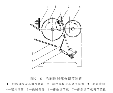
(6 ) Rear windshield: As shown in Figure 9-6, the rear windshield is located behind the brush drum, and is opposite to the pile support plate up and down to form a passage for the short pile to the pile collection tube. Its function is to cut the high-speed airflow layer on the surface of the brush drum and block the airflow from rotating around the brush drum, so that the short pile and airflow are blown to the short pile path and are not brought back to the upper space by the brush drum. Because the rear windshield blocks the airflow, a negative pressure is formed in the upper space of the brush roller. There is supplementary air between the front windshield and the saw blade roller to blow the short lint on the saw teeth.
You can use the adjusting nuts on both sides of the rear wall of the brush box to adjust the distance between the rear windshield and the brush. The appropriate gap is 1 to 2 mm.
2. Brush cover, impurity discharge adjustment plate, pile support plate and pile outlet
The brush cover is an arc plate concentric with the brush roller. At the front end of the brush cover, an upper trash knife and a trash baffle are installed to impact or block the impurities discharged from the upper trash area.
The impurity discharge adjustment plate and the pile support plate are also arc plates concentric with the brush roller. The impurity discharge adjustment plate can move forward and backward, up and down to adjust the amount of impurity discharge.
The size of the velvet outlet of the 144-type brush sawtooth stripping machine is 1744mm×80mm; the size of the outlet of the airflow sawtooth stripping machine is 1003mm×78mm.
AAASDFWERTEYRHF